Brendan Rudberg

Mechanical Engineering at Caltech - Controls & Robotics

Brendan Rudberg's headshot

My name is Brendan and I'm a junior at Caltech with a 4.0 GPA. I'm currently comparing data-driven and physics-based models for thermal systems and serving as the president of Caltech Racing, a rapidly growing formula SAE electric team. I'm majoring in mechanical engineering with a minor in robotics and a focus on control systems. In my free time you'll find me bouldering, pole vaulting, cooking, or playing Clash Royale. Scroll down to see some of the projects I've worked on!

Projects

Daedalus 3 Flap Design

States

x=[rz,  vz,  θ,  ω] x = [\,r_z,\; v_z,\; \theta,\; \omega\,]^{\top}

Dynamics

r˙z=vz\dot{r}_z = v_zv˙z=g1m ⁣[(Fflaps+Fbody)sinθ+Faxialcosθ]1mT(t)cosγ(t)\dot{v}_z = g - \frac{1}{m}\!\left[(F_\text{flaps} + F_\text{body})\sin\theta + F_\text{axial}\cos\theta\right] - \frac{1}{m}T(t)\cos\gamma(t)
Fflaps=12ρvzvzsinθ ⁣[2SfwdCN,fwdcosδfwd+2SaftCN,aftcosδaft]F_\text{flaps} = \tfrac{1}{2}\rho\, v_z|v_z|\sin\theta\!\left[2 S_\text{fwd} C_{N,\text{fwd}}\cos\delta_\text{fwd} + 2 S_\text{aft} C_{N,\text{aft}}\cos\delta_\text{aft}\right]Fbody=12ρvzvzArefCN,bodysinθF_\text{body} = \tfrac{1}{2}\rho\, v_z|v_z|\, A_\text{ref}\, C_{N,\text{body}}\sin\thetaFaxial=12ρvzvzArefCA,bodycosθF_\text{axial} = \tfrac{1}{2}\rho\, v_z|v_z|\, A_\text{ref}\, C_{A,\text{body}}\cos\theta
θ˙=ω\dot{\theta} = \omegaω˙=1I ⁣[Mflaps+Mbody+T(t)sinγ(t)rTVC]\dot{\omega} = \frac{1}{I}\!\left[M_\text{flaps} + M_\text{body} + T(t)\sin\gamma(t)\,r_\text{TVC}\right]Mflaps=12ρvzvzsinθ ⁣[2SfwdCN,fwdcosδfwdrfwd2SaftCN,aftcosδaftraft]M_\text{flaps} = \tfrac{1}{2}\rho\, v_z|v_z|\sin\theta\!\left[2 S_\text{fwd} C_{N,\text{fwd}}\cos\delta_\text{fwd}\, r_\text{fwd} - 2 S_\text{aft} C_{N,\text{aft}}\cos\delta_\text{aft}\, r_\text{aft}\right]Mbody=12ρvzvzCN,bodysinθAref(xCP(θ)xCG)M_\text{body} = \tfrac{1}{2}\rho\, v_z|v_z|\, C_{N,\text{body}}\sin\theta\, A_\text{ref}\,(x_\text{CP}(\theta) - x_\text{CG})

Constraint

Mhinge,i=12ρvzvzSiCN,isinθcosδidi    τservo M_{\text{hinge},i} = \tfrac{1}{2}\rho\, v_z|v_z|\, S_i C_{N,i}\sin\theta\cos\delta_i\, d_i \;\le\; \tau_\text{servo}

Dynamics equations for Daedalus 3. Y-axis symmetry is assumed.
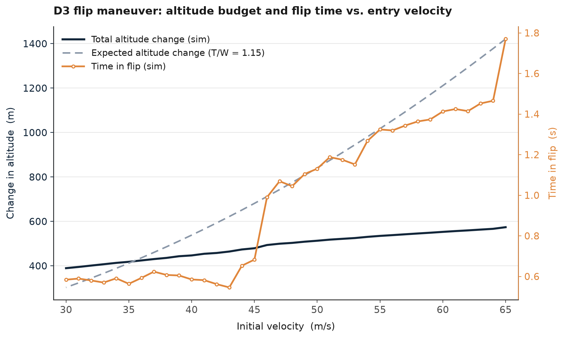
Change in Altitude vs. Entry Velocity for Daedalus 3
Altitude budget vs. entry velocity for a representative 0.01 m² flap design. Time-in-flip is also shown. It rises with entry velocity, but its point-to-point jitter reflects weakly determined schedule parameters: the altitude objective is nearly insensitive to them, so the optimizer's choice is not unique.
  • Own the aerodynamic flap design for Daedalus 3, a rocket-shaped bellyflop-to-vertical-landing drone at Parsec Rocketry, with responsibility for flap sizing, placement, hinge geometry, and the control-authority spec for the engine-off descent.
  • Derived a 4-state nonlinear coupled dynamics model of the bellyflop maneuver (vertical position, vertical velocity, pitch, pitch rate), with flap and body aerodynamic normal- and axial-force terms driving both translation and rotation.
  • Identified terminal velocity as the primary design driver, since arrest distance under a T/W near 1.15 scales with the square of terminal velocity, making belly-down drag maximization the core flap-sizing objective.
  • Built a nested optimization in Python (scipy) that sweeps hardware variables (forward and aft flap areas, moment arms, hinge offset) around an inner control-schedule tuning loop, integrating the vehicle dynamics via segmented solve_ivp calls with phase-transition events.
  • Showed that the full maneuver requires roughly 400 to 600 m of altitude, from a 30 m/s entry up to a terminal-velocity entry, establishing that a complete bellyflop from a self-propelled launch is impractical.
Stochastic State Space Modeling

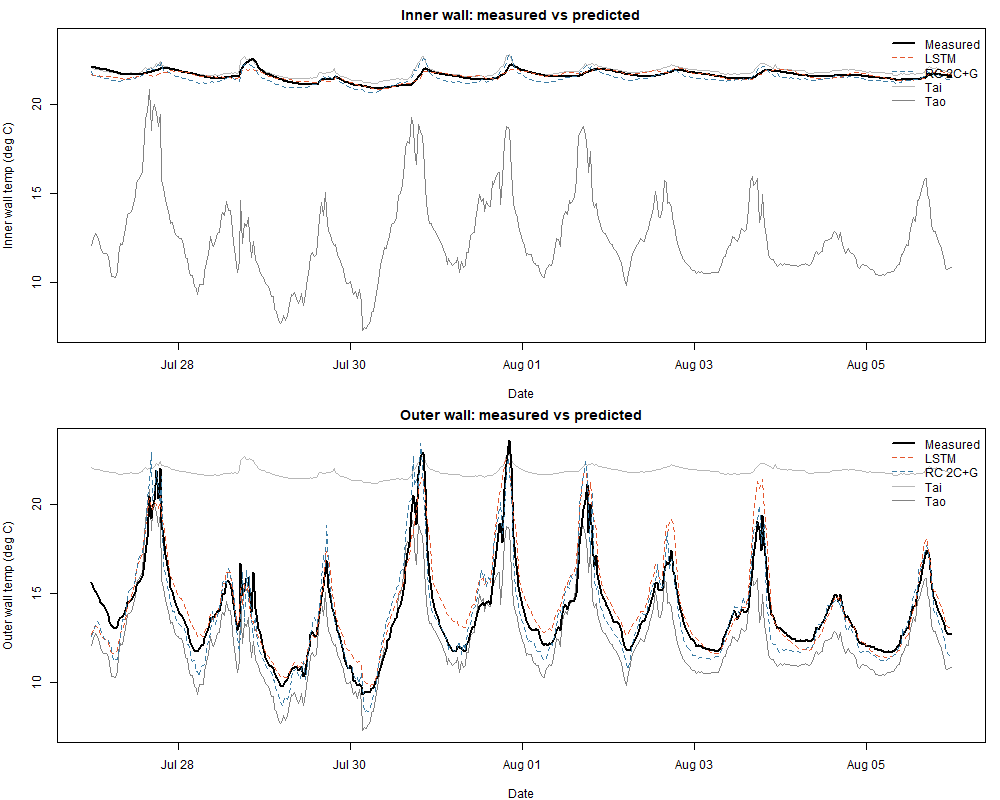
RC and LSTM model comparison to results
2-capacitor RC model compared to LSTM and experimental results on the test dataset.
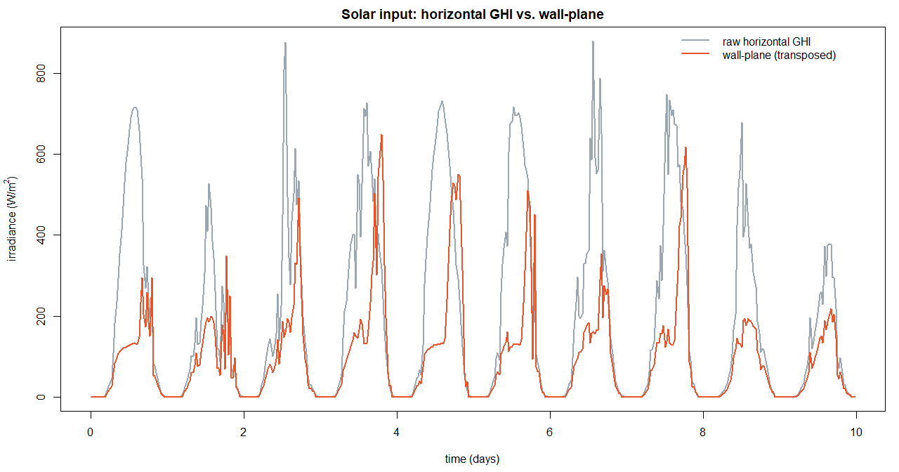
Solar irradiance transformation
Solar irradiance data, before and after geometric transformation.
  • Formulated grey-box RC-network state-space models of the building envelope's thermal dynamics, with air temperatures as boundary inputs and wall temperatures as observed states, keeping the lumped-parameter structure physically interpretable.
  • Instrumented the envelope with four DS18B20 1-Wire sensors logging to a Raspberry Pi, producing a clean 30-day passively-excited dataset for system identification.
  • Transposed horizontal solar irradiance onto the wall plane via solar geometry (sun position, angle of incidence), correcting for the horizontal-sensor / vertical-envelope mismatch.
  • Identified the wall model by maximum-likelihood estimation in continuous-time stochastic modeling (CTSM), comparing RC networks of increasing order by residual whiteness diagnostics.
  • Benchmarked against a graded lineup (persistence, static-linear, black-box state-space, and an LSTM) so held-out multi-step prediction error attributes to a single modeling ingredient at each rung.
  • 7-parameter grey-box matched the LSTM's out-of-sample accuracy where inputs were well-characterized and generalized more stably, while the LSTM led where drivers were unmeasured, quantifying the interpretability vs flexibility tradeoff.

Inverted Pendulum

Energy-based swing-up handing off to LQR balancing control on a cart-pole system
  • Leading a team of six, designed and built an inverted pendulum on a cart that swings the pendulum up from rest and holds it upright indefinitely under closed-loop control.
  • Architected the full control stack: an energy-based swing-up controller with an energy-gated handoff to an LQR balancing controller, so the system transitions automatically once the pendulum enters the capture region near vertical.
  • Implemented state estimation with a Kalman filter fusing encoder position and velocity, tuned to reject quantization noise without lagging the fast dynamics.
  • Built the hardware around a NEMA 17 stepper driven by a TMC2209, AMT10E2-V encoders for cart and pendulum angle, and an Arduino Nano ESP32 running the real-time loop.
  • Pivoted the actuation from a BLDC/SimpleFOC/Teensy stack to the stepper architecture after field-oriented control proved unreliable, recovering the timeline without dropping the demo target.

Caltech Racing - FSAE Electric

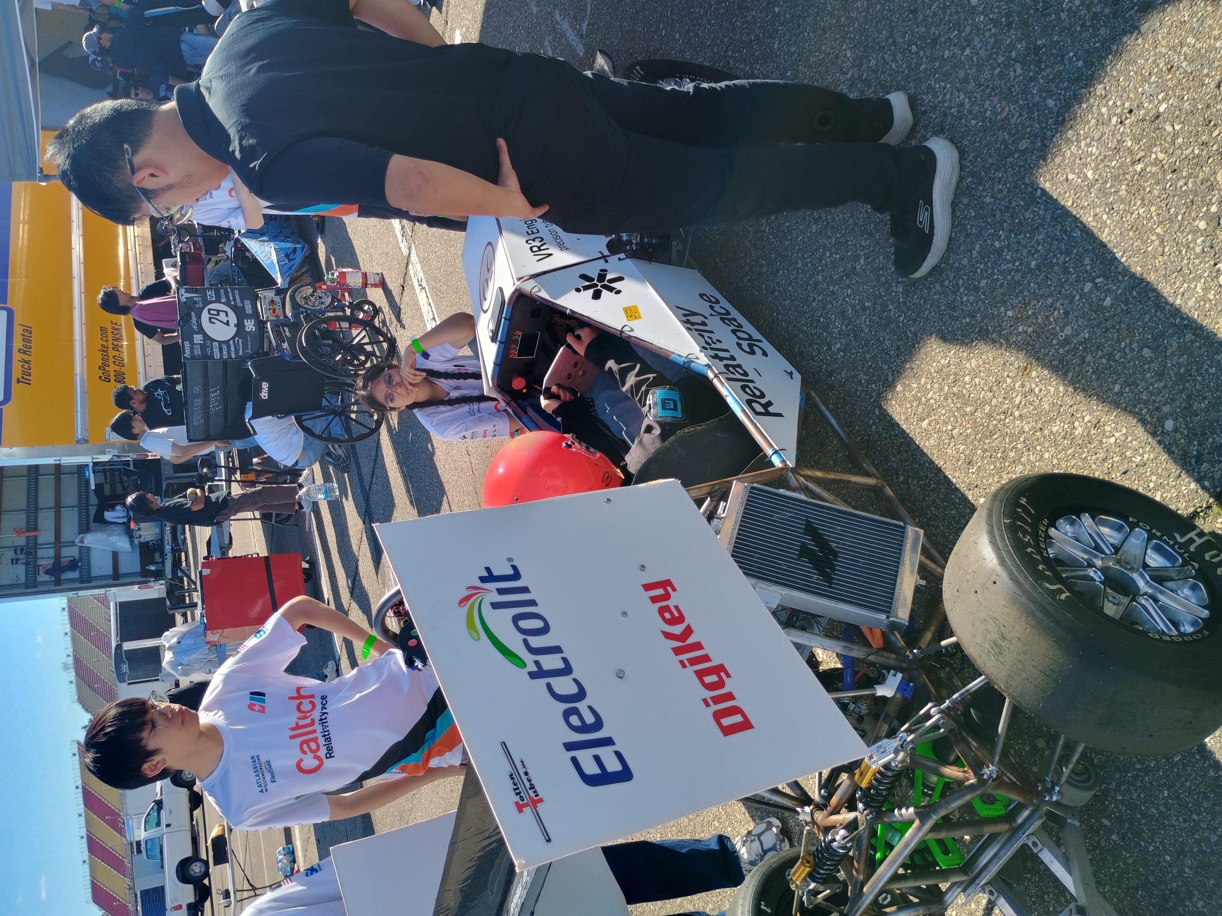
Formula SAE electric racecar
The rolling chassis we brought to the 2026 competition in Michigan.
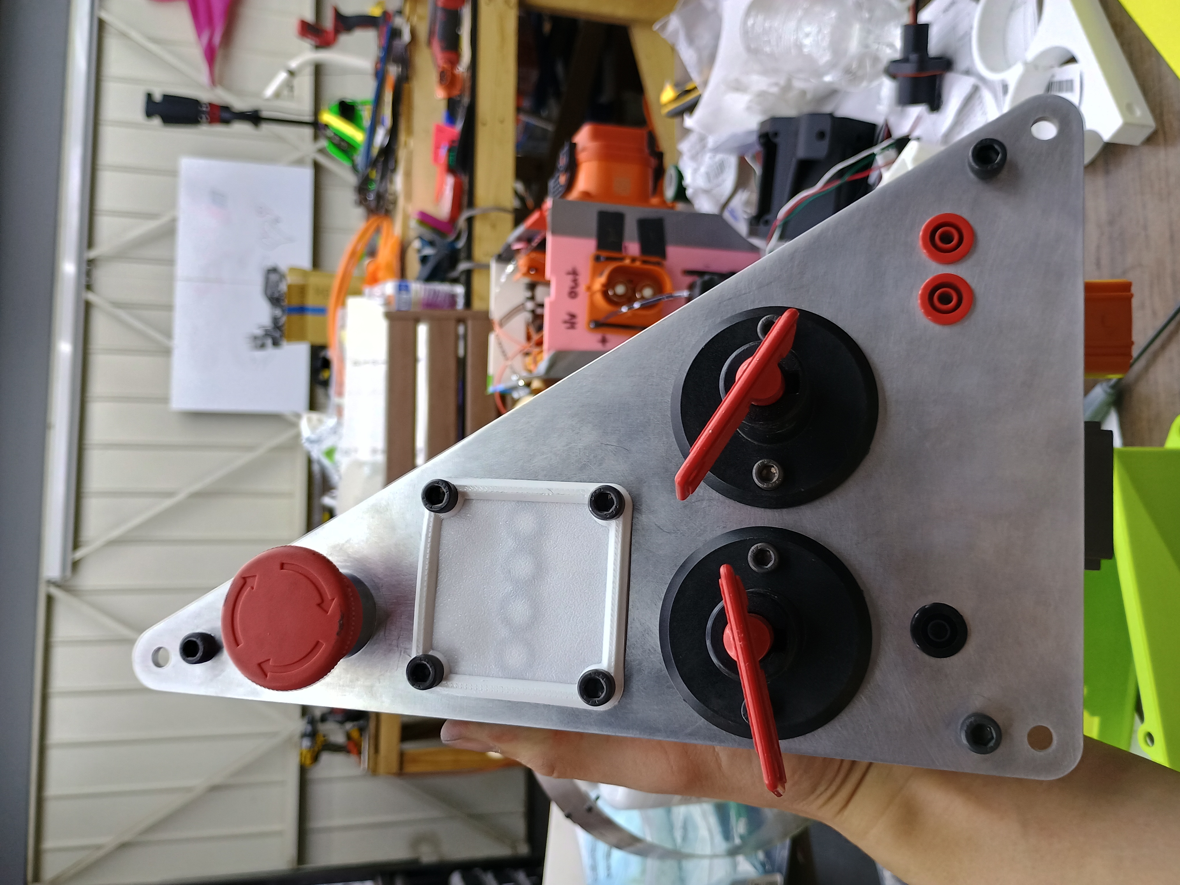
High voltage enclosure front
The control panel containing the shutdown button, fault-reset PCB interface, master switches, and voltage measuring points.
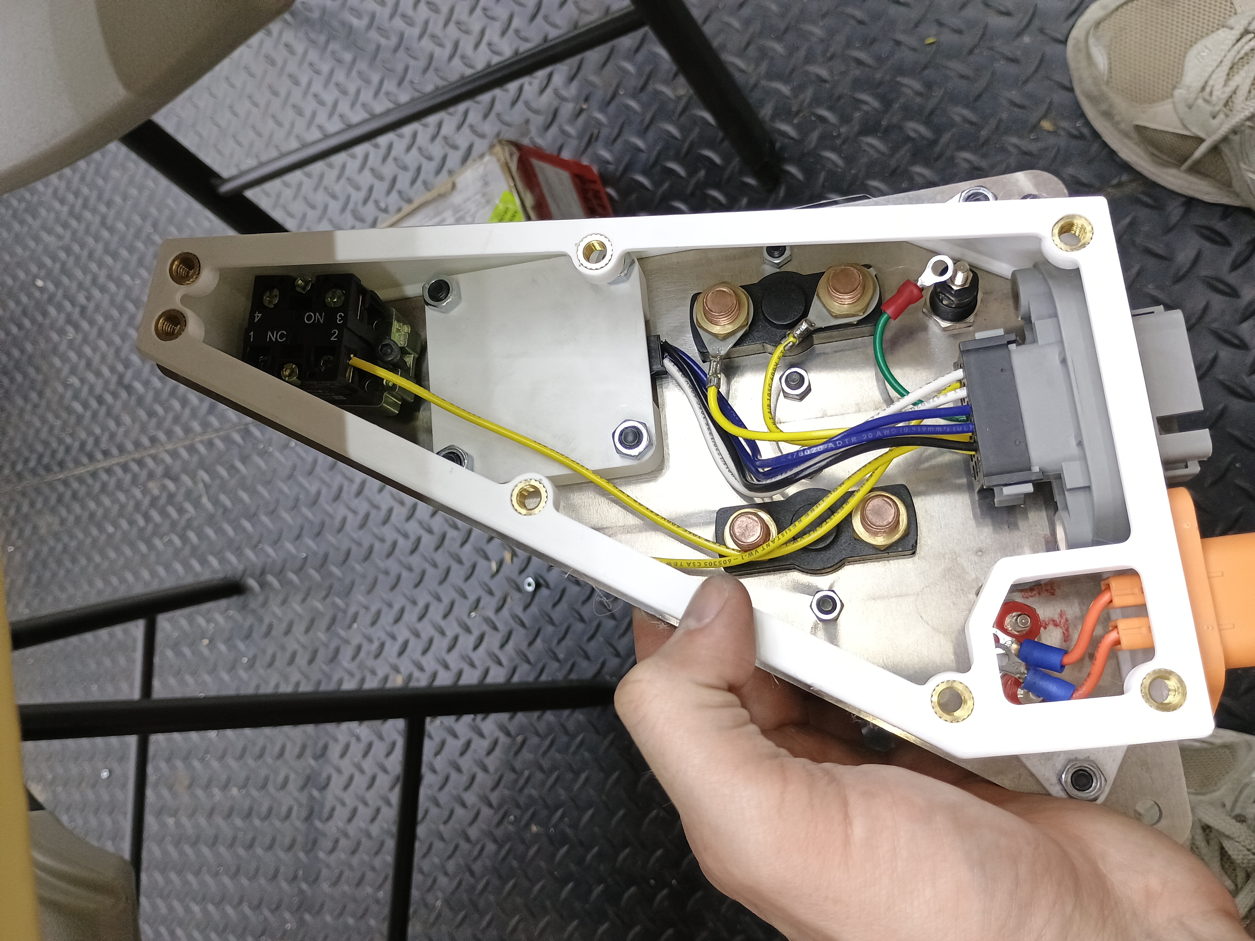
High voltage enclosure internals
High voltage enclosure internals.
  • Designed and built a waterproof electronics enclosure for an externally-accessible panel on the Caltech Racing FSAE Electric car, housing the fault-reset PCB, shutdown buttons, master switches, and tractive system measuring points (TSMPs) in a tightly packaged volume.
  • Engineered a custom TPU membrane that flexes under finger pressure to actuate the underlying buttons through the enclosure wall, sealing the PCB against water ingress while preserving driver access to safety-critical controls.
  • Integrated the membrane into a 3D-printed PETG body with an aluminum front plate, balancing manufacturability and weight against the rigidity needed to hold the membrane geometry under repeated actuation.
  • Navigated FSAE rules compliance for HV/LV separation, working through material selection (PETG vs. nylon, garolite barriers) and TSMP spacing requirements against the 2026 rulebook.
  • Owned the design end-to-end in SolidWorks: part modeling, assembly, GD&T drawings, and tolerance stack-up for the press-fit interfaces between the membrane, body, and front plate.

Autonomous Exploration Robot

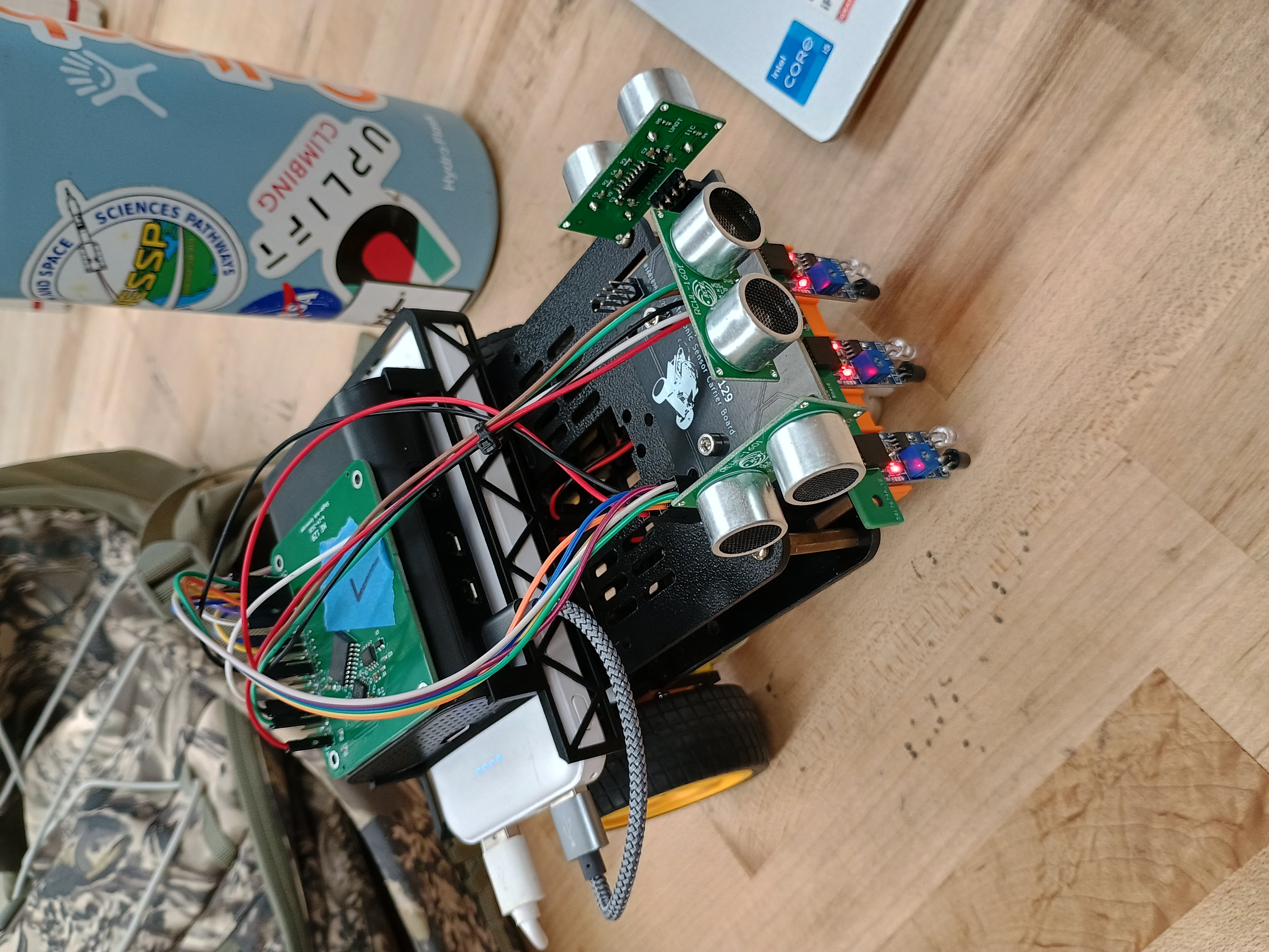
Autonomous exploration robot
Teriyaki, the autonomous exploration robot.
  • In a team of two, built a robot that line-follows through an unknown street grid, maps it autonomously, and navigates to commanded goals while routing around obstacles.
  • Implemented line and street following from a 3-sensor IR array, using filtered edge detectors (exponential smoothing with hysteresis) for robust intersection and dead-end detection, with a gyroscope integrating turn angle to resolve discrete heading changes across 8 compass directions.
  • Built an incremental map of intersections and street states (unexplored / connected / dead-end / blocked) and layered Dijkstra path planning on top for both goal-directed navigation and autonomous exploration that targets the nearest unfinished intersection.
  • Fused 3 ultrasonic sensors for multi-threshold blockage detection (20 / 65 / 92 cm) feeding dynamic replanning with blockage-clear retries and directed exploration fallback when no known route exists, plus an NFC reader tagging intersection IDs.
  • Architected the system across concurrent threads (planning brain, terminal UI, ultrasonic triggering, NFC polling) with a ROS 2 node publishing live pose and subscribing to goal/explore commands.
  • Fully mapped an unknown test grid and reliably planned efficient routes between arbitrary points, staying robust to sudden blockages and path defects introduced mid-run.

Dual Shifting Transmission

An example of our transmission shifting. Play unmuted to hear it working!
  • Designed and built a two-speed passive-shifting transmission with a six-person team for the ME14 design competition under a $250 budget.
  • Implemented a roller-clutch freewheeling mechanism on both stages to enable passive shifting via motor reversal.
  • Replaced a four-part keyed hub with a press-fit acetal-on-steel joint, verified by Lamé analysis (SF ≈ 13-14 on radial stress, ≈ 2-3 on transmitted torque), cutting machining from 4 parts to 2.
  • Won 1st place in the ME14 design competition on combined acceleration and steady-state power.

Object Tracking Robot

A demonstration of mechanical object tracking using computer vision.
  • Designed and implemented a real-time vision-based object tracking robot using camera input and motorized actuation.
  • Performed color-based segmentation by converting RGB frames to binary masks isolating target objects by color and size.
  • Computed object centroids and mapped image-space coordinates to relative positional error for closed-loop control.
  • Generated smooth motor trajectories using spline interpolation for stable camera and platform motion.
  • Developed a multithreaded software architecture enabling concurrent image acquisition, processing, and motor control.

Photonic LiDAR Research - UW Mo Li Group

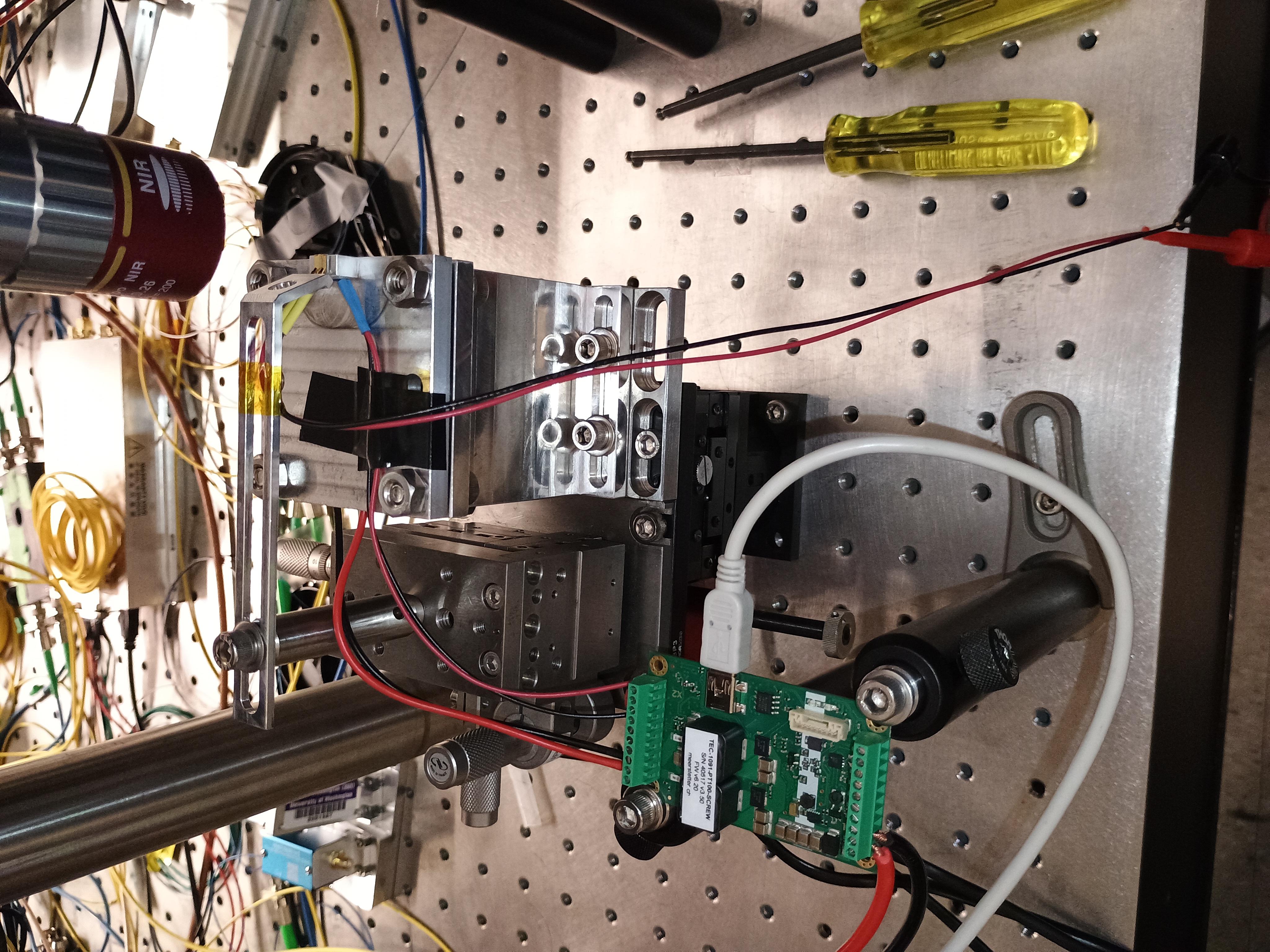
Heatsink with TEC and laser chip
Custom designed heatsink with a laser chip running a temperature control PID loop.
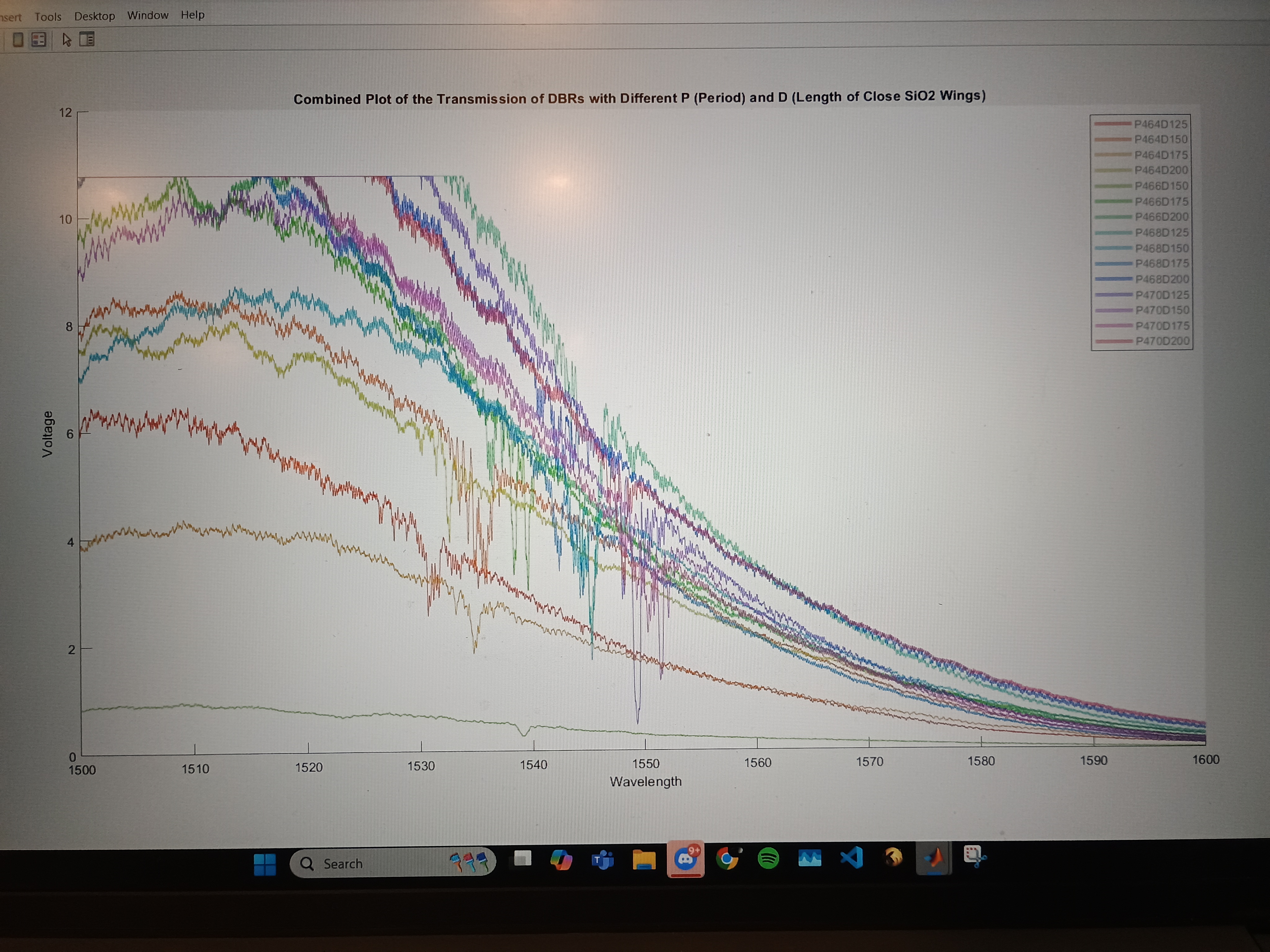
A graph containing a series of transmissions for different DBRs
A plot of the spectral transmission for a bunch of DBRs I made.
  • Designed integrated distributed Bragg reflectors (DBRs) for chip-scale beam-steering lasers, targeting a Δn ≈ 10⁻³ refractive-index contrast to balance reflection bandwidth against device footprint.
  • Iterated through three design generations (V1 sinusoidal sidewalls, V2 refined groove geometry, V3 wing-style DBR with SiO₂ cladding), using COMSOL FDE eigenmode simulations to guide each revision.
  • Achieved an 84% footprint reduction and 3× reflectance improvement over a published baseline through the V1→V3 design progression.
  • Designed chip layouts in GDSFactory and fabricated devices via HSQ direct-write electron-beam lithography, which converts to SiO₂ on exposure, combining mask and deposited cladding in a single step for the nanometer-scale V3 features.
  • Built a custom heatsink and thermoelectric cooling (TEC) setup with a dedicated TEC controller, closing a PID loop to stabilize chip temperature to ±0.01°C during characterization.
  • Characterized fabricated devices using a Fourier-domain optical filtering setup, validating simulated reflectance and bandwidth against measured performance.

Indoor V10

The hardest project I've worked on.

Thanks for making it this far! More projects on the way.